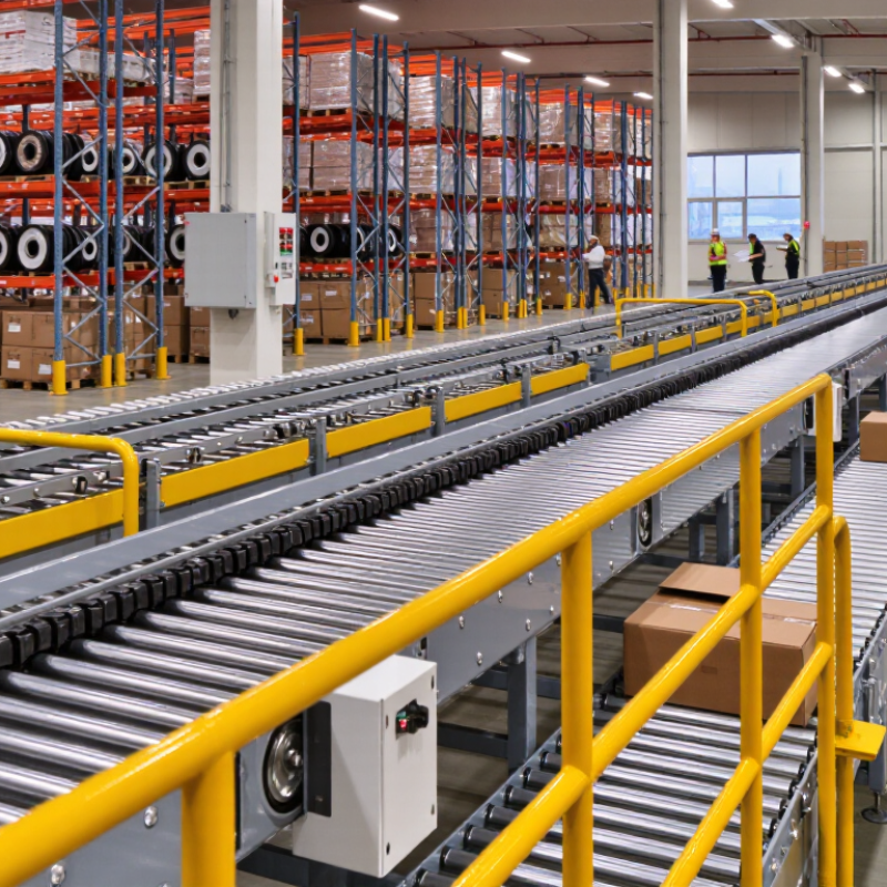
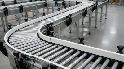
Choosing the right conveyor parts for global sourcing is not simply a price comparison. It is a reliability decision. A belt splice, pulley, idler, or scraper may look interchangeable in a supplier catalogue. In operation, small differences can create major downtime. Belt width, load weight, material abrasiveness, operating temperature, and conveyor speed must match the application. They must also match each other.
As conveyor specialist R. Todd Swinderman observes, “A conveyor is a system, not a collection of parts.” That principle should guide every sourcing decision. Experienced buyers examine drawings, material certificates, test reports, warranty terms, and replacement lead times. They also ask practical questions. Can the supplier maintain dimensional consistency? Are wear parts available near the operating site? Has the component worked in a similar environment?
Global sourcing adds another layer of risk. Packaging damage, unclear tolerances, inconsistent steel grades, and communication gaps can weaken an otherwise suitable purchase. A low quotation may become expensive after freight, inspection, installation, and emergency replacement costs. This is where technical expertise matters. Compare suppliers by total operating value, not only unit price. Request samples when possible. Test critical conveyor parts before full-scale approval.
The process is rarely perfect. I have seen specifications that looked complete but missed cleaning conditions or seasonal temperature changes. That gap deserves attention. A careful sourcing plan includes site feedback, documented inspections, and a realistic backup option. When engineering requirements, supplier evidence, and field experience agree, conveyor parts become dependable components rather than uncertain catalogue items.
Global conveyor sourcing starts with a measurable duty, not a component catalogue. Define capacity in tonnes per hour, belt speed in metres per second, and material load in kilograms per metre. CEMA’s Belt Conveyors for Bulk Materials, 7th Edition, and ISO 5048 support this calculation approach. The basic relationship is Q = 3.6 × M × V, where Q is capacity, M is linear load, and V is speed.
For example, a conveyor carrying 200 kg/m at 1.5 m/s handles approximately 1,080 t/h. That number is only useful when the load reflects real bulk density, belt fill, moisture, and incline. A 20% capacity margin can protect against seasonal density changes and uneven feeding. Do not hide the peak rate. Specify both average and maximum duty.
I once reviewed a specification showing 1,000 t/h, but it omitted the kilogram-per-metre load. That gap made pulley, idler, belt, and drive selection uncertain. A better sourcing sheet records material density, lump size, loading method, operating hours, ambient temperature, and duty cycle. It also states whether speed is fixed or variable. ISO 5048 calculations still require engineering judgment around starts, transfers, and take-up forces. The formula is simple. The assumptions are not. Use SI units, shared test methods, and documented tolerances when comparing suppliers across countries.
Define conveyor duty using capacity, belt speed, and distributed load before selecting belts, rollers, pulleys, drives, and bearings.
The bars show representative material throughput in tonnes per hour. Hover over each bar to compare belt speed and distributed load. Higher capacity, speed, or load generally requires stronger belt construction, larger rollers and pulleys, higher drive torque, and more robust bearings.
How to Choose the Right Conveyor Parts for Global Sourcing?
A belt is not a capacity number. Its loading geometry matters. CEMA 7th Edition tables relate capacity to belt width, speed, trough angle, idler spacing, and material surcharge angle. Start with measured bulk density, not a supplier’s optimistic estimate. IEA’s Coal 2023 report recorded global coal demand at about 8.3 billion tonnes in 2022. That scale makes small calculation errors expensive. Confirm moisture and lump size, too.
ISO 5048 calculates conveying capacity from cross-sectional load area, belt speed, and bulk density. For example, an 800-millimetre belt carrying material at 1.5 metres per second may use an area of 0.035 square metres. At 1.6 tonnes per cubic metre, the theoretical rate is about 202 tonnes per hour. Inclination, loading efficiency, and spillage reduce this figure. Do not order pulleys or idlers from capacity alone. Shaft loads and belt tension still need checking.
I once treated catalogue capacity as a design value. That was a mistake. A better sourcing sheet records the CEMA table assumptions and the ISO calculation separately. Specify pulley diameter, bearing loads, belt cover, idler seal type, and operating temperature. Leave traceable tolerances. The numbers may look precise, but field material rarely behaves perfectly. Recheck the design when density changes.
Selecting an idler begins with the real load, not only the belt width. Calculate belt tension, material weight, impact forces, and the spacing between idlers. A lightly loaded transfer point may still create sharp impact loads. Choose an idler load rating above the calculated working load, with a practical safety margin. Do not use an attractive catalogue number without checking test conditions.
Bearing L10 life describes the point when 90% of identical bearings should still operate under stated conditions. Estimate equivalent bearing load, rotational speed, operating hours, and contamination levels. Sealed bearings may need extra protection in dusty or wet environments. Shaft deflection also deserves attention. Excessive deflection can misalign the shell, increase rolling resistance, and overload bearings. Ask for shaft diameter, material, span data, and allowable deflection. Field experience shows that small design assumptions can become costly after installation.
Tips: Request load curves, dimensional drawings, material certificates, and inspection records from each supplier. Compare identical duty conditions. Check whether ratings include impact loads. Review bearing calculations independently. The first estimate is rarely perfect. Leave room for correction when actual bulk density, moisture, or belt tension differs from the original data.
When sourcing conveyor parts globally, specify the motor’s IEC 60529 IP rating before comparing prices. The rating describes protection against solids and water. IP55 protects against dust deposits and water jets. IP66 offers stronger sealing for washdown areas. Do not treat these ratings as interchangeable.
Check the real environment. A dusty warehouse may need IP55, while a wet food-processing zone may require IP66 or higher. Cable glands, terminal boxes, and mounting positions can weaken protection. I have seen otherwise suitable motors fail because a poorly sealed connector allowed moisture inside. Small details matter.
Duty class is equally important. Continuous operation often requires S1 duty, while frequent starting may require an intermittent class such as S3. Match the motor and gearbox to running hours, starts per hour, load weight, belt speed, and acceleration time. The gearbox also needs an appropriate service factor, not merely the correct output speed. A motor can meet its rated power and still overheat under repeated starts.
Request datasheets, performance curves, IP test evidence, duty classification, and temperature limits from each supplier. Confirm whether ratings apply to the complete assembly or only the motor housing. This distinction is easy to miss. Specify voltage, frequency, efficiency requirements, brake options, shaft dimensions, and ambient temperature in one controlled document. Leave less room for assumptions. Yet, even detailed specifications can need revision after site testing, especially when dust, washdown pressure, or conveyor loading differs from the original estimate.
| Selection Dimension | Typical Conveyor Condition | Recommended Specification | Relevant Rating or Standard | Global Sourcing Checkpoint |
|---|---|---|---|---|
| 1. Motor and Gearbox Environmental Protection | ||||
| Indoor, dry and clean area | Limited dust, no direct water exposure, stable ambient conditions. | Use a motor and gearbox with a sealed enclosure suitable for the installation environment. A minimum of IP54 is commonly specified for general industrial indoor equipment. | IEC 60529 defines the IP code. The first digit addresses solid-object and dust protection; the second digit addresses water protection. | Confirm the complete assembly rating, not only the motor rating. Check whether the terminal box, cable glands, brake and encoder have compatible protection. |
| Dusty production area | Conveyor operates near bulk materials, powders, fibers or dry particulate matter. | Specify at least IP55 where dust ingress and water-jet cleaning may occur. Consider IP65 when dust-tight protection is required. | IEC 60529: 5 indicates protection against dust that could interfere with operation; 6 indicates dust-tight protection. The second digit 5 indicates protection against water jets. | Verify that the gearbox seals and breather arrangement are suitable for dusty service. A higher IP rating does not automatically confirm chemical, corrosion or explosion protection. |
| Frequent washdown or wet area | Water splashing, hose cleaning or regular exposure to moisture. | Use a washdown-compatible motor and gearbox with a suitable enclosure, corrosion-resistant external surfaces and protected cable entry. IP65 or IP66 may be appropriate depending on the cleaning method. | IEC 60529: 6 as the second characteristic digit indicates protection against powerful water jets. | Do not select solely by IP code. Confirm seals, shaft protection, drain-hole configuration, paint or stainless construction, and compatibility with cleaning chemicals. |
| Temporary immersion risk | Equipment may be exposed to flooding, deep pooling or accidental immersion. | Specify an enclosure tested for the actual immersion condition, such as IP67 for temporary immersion where applicable, or IP68 when the manufacturer states the defined continuous-immersion conditions. | IEC 60529: the second digit 7 concerns temporary immersion; 8 concerns continuous immersion under conditions specified by the manufacturer. | Ask for the test conditions and installation limits. IP67 does not imply IP66 performance unless both ratings are explicitly stated. |
| 2. Duty Class and Operating Profile | ||||
| Continuous conveying | Conveyor runs for long periods at a substantially constant load and speed. | Specify continuous-duty operation, normally IEC 60034-1 S1, with rated power based on calculated belt or chain pull, speed, efficiency and service conditions. | IEC 60034-1 defines duty types. S1 is continuous running duty: operation at a constant load for sufficient time to reach thermal equilibrium. | Provide operating hours per day, starts per hour, speed range, load profile and ambient temperature to the motor supplier. |
| Intermittent conveying | Repeated load and rest cycles, such as indexing, accumulation or batch transfer. | Evaluate S3 intermittent periodic duty or another applicable duty type. State the cycle duration and duty-cycle percentage rather than selecting only by nominal motor power. | IEC 60034-1 S3 describes intermittent periodic duty where starting has no significant effect on temperature rise. The duty-cycle percentage is essential for comparison. | Include starts per hour, run time, rest time, braking method and peak torque. Confirm that the gearbox can withstand repeated acceleration loads. |
| Frequent starting and stopping | High number of starts, stops, reversals or rapid acceleration cycles. | Consider a motor duty appropriate to starting and braking, such as S4 where starting significantly affects temperature rise. Size for peak torque and thermal cycling. | IEC 60034-1 S4 covers intermittent periodic duty with starting. The starting frequency and load inertia must be stated. | Check motor starting current, brake response, inverter compatibility, shaft torque, coupling limits and gearbox peak-load capacity. |
| Variable-speed conveyor | Speed changes according to product flow, accumulation or process demand. | Use an inverter-compatible motor and confirm the required constant-torque or variable-torque speed range. Verify cooling at low speed and maximum permissible operating frequency. | Motor duty classification should be considered together with the drive system, thermal limits and actual load cycle. | Specify minimum and maximum speed, acceleration time, braking energy, control voltage, frequency range and required feedback device. |
| 3. Mechanical Sizing | ||||
| Required conveyor power | Power depends on conveyed mass, belt or chain resistance, lift, speed and mechanical efficiency. | Calculate the required torque and power at the conveyor shaft before choosing the motor. Allow for friction, incline, acceleration and auxiliary loads. | Use the conveyor manufacturer’s engineering method and applicable design practices. Do not infer motor size from belt width alone. | Submit belt or chain type, conveyor length, inclination, material mass flow, starting condition, roller data and target speed for quotation. |
| Gearbox output torque | Gearbox must transmit continuous torque and withstand starting, stopping and occasional overloads. | Select a gearbox with continuous output torque above the calculated operating torque and verify peak or emergency torque separately. | Gearbox torque ratings are manufacturer-specific; compare the defined rating conditions, service factor and allowable overload. | Request the rated output torque, permissible radial and axial loads, thermal rating, ratio, efficiency and declared service factor. |
| Reduction ratio and output speed | Motor speed must be reduced to the required conveyor shaft speed. | Choose the ratio from the required output speed and motor operating speed. Confirm that the selected ratio does not force the motor outside its efficient or permissible speed range. | Ratio, rated speed and output speed should be stated under defined frequency, load and slip conditions. | Specify nominal speed, acceptable speed tolerance, output shaft orientation, mounting position and direction of rotation. |
| Overhung load and shaft arrangement | Sprockets, pulleys or belt drives impose radial and sometimes axial forces on the gearbox output shaft. | Check gearbox allowable radial and axial loads at the actual distance from the bearing. Use an appropriate hollow-shaft, keyed, shrink-disc or solid-shaft arrangement. | Allowable loads are equipment-specific and must be checked against the selected mounting and service conditions. | Provide pulley or sprocket diameter, transmitted force, shaft extension, overhung distance, coupling type and mounting orientation. |
| 4. Electrical and International Sourcing Requirements | ||||
| Power supply compatibility | Equipment may be installed in different countries or production sites. | State rated voltage, frequency, phase, connection method and allowable voltage tolerance. Confirm compatibility with the local electrical system or variable-frequency drive. | Electrical characteristics must be defined on the motor nameplate and technical datasheet. IEC standards may be supplemented by local installation requirements. | Request drawings showing terminal-box position, cable-entry thread, mounting dimensions, shaft dimensions and nameplate data in the required units. |
| Motor efficiency | Conveyor operates many hours per day and energy consumption is a significant lifecycle cost. | Specify the applicable efficiency class for the target market and operating point. Compare efficiency at the actual load and speed, not only at rated output. | IEC 60034-30-1 defines efficiency classes for many line-operated AC motors; applicability depends on motor type and rating. | Ask for efficiency data, power factor, current, losses and test conditions. Verify local minimum-efficiency regulations before purchase. |
| Documentation and conformity | Imported components must be traceable, installable and acceptable to the destination market. | Require a datasheet, dimensional drawing, wiring diagram, declaration or certificate applicable to the destination, test records and maintenance instructions. | IEC 60529 IP claims should be supported by documented test information or a clear manufacturer declaration. Duty classification should be stated according to IEC 60034-1 where applicable. | Use the same technical schedule for all suppliers so that IP rating, duty class, torque, ratio, dimensions and delivery scope can be compared consistently. |
| Spare parts and serviceability | Downtime risk is high when motors, gearboxes or seals are sourced internationally. | Define replaceable bearings, seals, brakes, fans, terminal components, couplings and lubricant requirements. Keep critical spare units or repair kits where justified. | Maintenance intervals and lubricant specifications are equipment-specific and should be supplied with the gearbox and motor documentation. | Confirm spare-part availability, lead time, packaging, preservation for transport, warranty terms and interchangeability of key dimensions. |

Global sourcing should begin with measurable supplier evidence, not attractive pricing. The 2024 MHI Annual Industry Report found that 55% of respondents expected to adopt artificial intelligence within five years. This highlights a wider need for better supply-chain visibility. Ask suppliers to share live production capacity, inspection records, and shipment history. MOQ must match your replacement cycle. A low MOQ can still create excess inventory and hidden storage costs.
Lead time needs two numbers: standard production time and realistic replenishment time. Request written ranges for bearings, rollers, belts, and drive components. Then check tolerances against your drawings, not catalog descriptions. Verify shaft diameter, roller runout, belt width, hole position, and bearing fit. A small mismatch can cause tracking faults, vibration, or premature wear. In my sourcing experience, suppliers often confirm “standard tolerance” without defining the actual limit. That needs correction.
Tips: Build a supplier scorecard with MOQ, lead time, tolerance data, inspection method, and corrective-action history. For CE compliance, ask whether the part requires CE marking under its applicable European product rules. Request the Declaration of Conformity, risk information, technical documentation references, and installation instructions when relevant. CE status may change after integration into a complete conveyor system. Treat missing paperwork as a technical risk, not simple administration. Audit samples before approving mass production. Cost savings are useful, but repeatability matters more.